Advanced Electromagnetic Ray Tracing Methods
Advanced Ray-Tracing Algorithms
- Ray-tracing is a convenient method to characterize wave propagation in electrically large and complex environments.
- Computational costs much smaller compared to full-wave solvers such as FEM or MoM.
- No increase in run-time or memory with increasing frequency.
- Great potential for parallelization with GPU: Fast simulations.
- Typical applications:
- Radar cross section (RCS) computations.
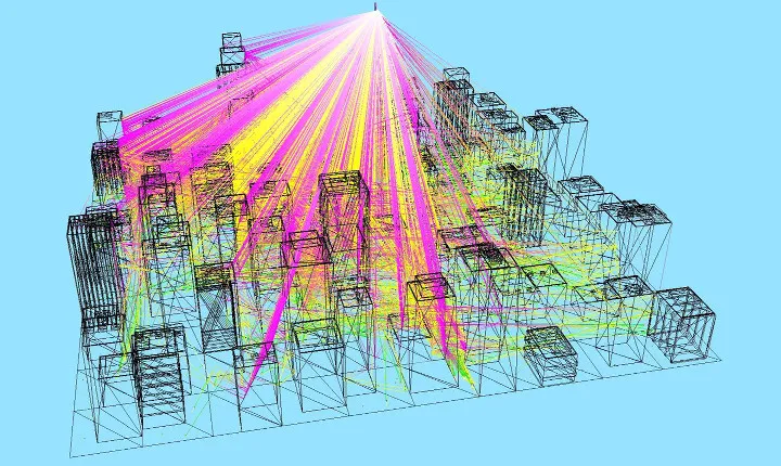
- Wireless network simulations in virtual environments.
- Automotive applications: radar, communication.
- Planning of indoor/outdoor mobile systems.


Principles
- Mostly based on Geometrical Optics and Uniform Theory of Diffraction (GO/UTD).
- Physical Optics (PO) for scattering problems.
Geometrical Optics Approach
- Approximation of Maxwell’s equations for high-frequency (ω→∞).
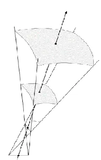
- Propagation of energy along straight lines, i.e, the rays.
- Conservation of energy: Diverging ray tubes.
- Propagation path satisfies the principle of least time (Fermat’s principle).
Reflection & Refractions (Snell’s Law)


Uniform Theory of Diffraction
- Fields in shadow regions are ignored in GO.
- UTD is utilized to compute those contributions.
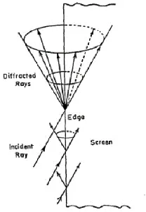
- Straight edges are considered.
- A single incident ray upon the edge may create thousands of new rays on Keller cone.
Generation of Rays
Two approaches
1. Method of Images
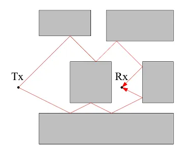
- All feasible ray paths between receiver-transmitter are obtained deterministically by image theory.
- Preprocessing required.
- Complexity increases exponentially with the number of the interactions.
2. Shooting and Bouncing Rays (SBR)
- Launch many rays in arbitrary directions.
- Rays are traced until stopping criteria is met.
- No preprocessing required.
- Linear increase in complexity with the number of interactions.
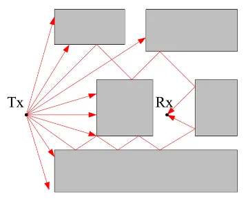
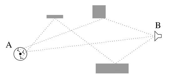
Reception of Rays

- Spheres are placed at receiver locations.
- Rays are collected if they hit the sphere.
- Sphere size should be chosen carefully.
- Large spheres: Many incorrect contributions might be captured.
- Small spheres: Relevant contributions might be missed.
- Number of ray launches should be large if the environment is large and complex.
Novel Approaches
Typical Problems of Traditional Ray-Tracing Techniques
- Problems with reception spheres:
- Reception spheres should typically be small to prevent incorrect rays to be captured.
- Small spheres implies a large number of ray launches to ensure relevant contributions are captured.
- Large number of ray launches → increase in complexity.
- Problems with UTD-based diffraction computations:
- The number of rays may grow rapidly, especially when multiple diffractions are involved.
- Accuracy problems with multiple diffraction scenarios when the propagation path is at the optical boundaries.
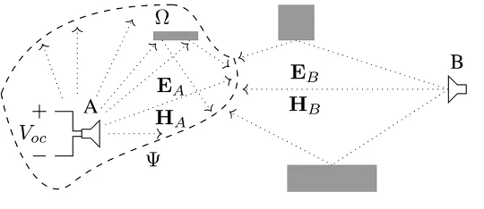
TUM HFT Approach
- Instead of launching rays from a single antenna (unidirectional), both antennas are used for ray launching (bidirectional).
- Rays are captured on a large interaction surface, instead of small spheres.
- Coupling is computed by evaluating reciprocity integrals on the surface.
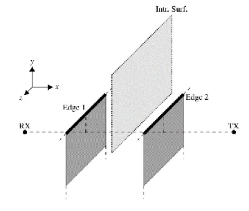
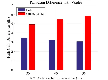
Bidirectional Ray-Tracing for Diffraction Scenarios
- A large, open surface is placed above the diffraction edge(s) where the antennas can directly hit the surface.
- No new rays are generated, computation time does not increase.

Examples & Results
- The bidirectional ray-tracing method demonstrates a better accuracy than unidirectional ray-tracing when the scenario grows in size, i.e., the distance between the antennas.


- Double knife-edge diffractions near optical boundaries can be simulated with a better accuracy and by tracing a smaller number of rays, hence, with a smaller computational effort.

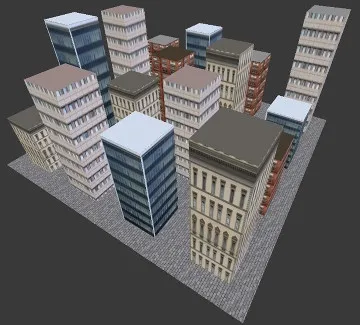
Application Examples
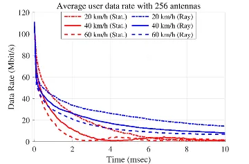
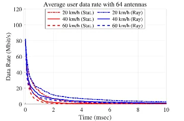
Characterization of Channel Aging Effects in Massive MIMO
- Massive MIMO relies on accurate channel information for beamforming.
- Channel state information becomes quickly obsolete when users are mobile. Channel aging → reduced performance.
- Small urban scenario with 64 mobile users (vehicles).
- Channel state information is not updated.
- Decline of the average data rate has been investigated.
- Comparisons with a statistical channel aging model.
- Utilizing large number of TX antennas (256 vs. 64) alleviates the drastic decay.
Conclusion
- Improvements over the state-of-the-art in terms of computational speed and accuracy.
- Useful in practically relevant propagation environments, e.g., urban, suburban.
- Various application areas: Massive MIMO, Radar, V2X communications.
Literature
- Z. Yun and M. F. Iskander, "Ray Tracing for Radio Propagation Modeling: Principles and Applications", IEEE Access, vol. 3, pp. 1089-1100, 2015.
- R. Kouyoumjian, P. Pathak, "A Uniform Geometrical theory of Diffraction for an Edge in a Perfectly Conducting Surface", Proceedings of the IEEE, vol. 62, no. 11, 1974.
- R. Brem and T. F. Eibert, "A Shooting and Bouncing Ray (SBR) Modeling Framework Involving Dielectrics and Perfect Conductors", IEEE Transactions on Antennas and Propagation, vol. 63, no. 8, pp. 3599-3609, 2015.
- M. S. L. Mocker, M. Schiller, R. Brem, Z. Sun, H. Tazi, T. F. Eibert and A. Knoll, "Combination of a Full-Wave Method and Ray Tracing for Radiation Pattern Simulations of Antennas on Vehicle Roofs", European Conference on Antennas and Propagation (EuCAP), Lisbon, 2015.
- M. M. Taygur, I. O. Sukharevsky and T. F. Eibert, "A Bidirectional Ray-Tracing Method for Antenna Coupling Evaluation Based on the Reciprocity Theorem", IEEE Transactions on Antennas and Propagation, vol. 66, no. 12, pp. 6654-6664, 2018.
- M. M. Taygur, I. O. Sukharevsky and T. F. Eibert, "Computation of Antenna Transfer Functions with a Bidirectional Ray-Tracing Algorithm Utilizing Antenna Reciprocity," URSI Atlantic Radio Science Conference, Gran Canaria, 2018.